Autonomous Can-Collecting Robot
As part of a graduate course in Mechatronics at Purdue, we were tasked with a challenge of building an autonomous robot that would collect and deposit cans from and to specified locations. This gave me the opportunity to combine my experience in CAD and design with a hardware build. This was executed by a team of four: Denise Hickman, Tim Sullivan, Harshal Charhate, and yours truly.
Challenge
The requirements were to build an autonomous, line-following robot that would traverse a path laid down with black tape, to a given marked-out space within which five half-pound cans were placed at random. The robot needed to pick up the cans, move to another specified location with a chute, and drop the cans into the chute. One of the cans was colder than the others, and bonus points were awarded if this can was dropped last. The robot needed to be placed in a “start” position, after which it would receive no human interference until the task ended. The robot, at the time of starting, needed to fit in a 12 in. $\times$ 12 in. $\times$ 12 in. envelope. Finally, there was a cost ceiling of $300.
My Role
I took on the responsibility for the bulk of the design and CAD (computer-aided design) modeling of the robot assembly, and of the Arduino programming.
Design Process and Iterations
In this article, I will focus on the design of the robot, but the report at the end (see link to pdf file at the bottom of this page) includes all details including wiring diagram, bill of materials, and Arduino code. After an initial brainstorming process, we decided upon a radial layout to carry the cans: this would be the most compact given our size restrictions. We also decided that we would hoist and carry the cans on a platform, instead of dragging them. With these decisions in mind, we created a rough concept sketch.
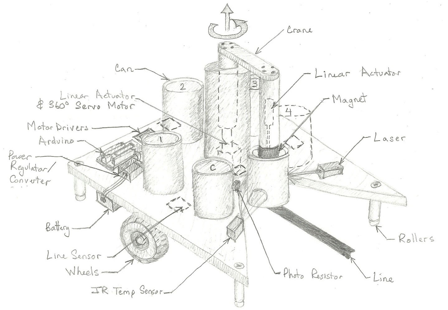
An initial sketch of the robot showed our intent to hoist
and carry the cans.
The cutout at the front was to guide the cans to the pick-up
point, where the boom would use a gripper or a magnet to
pick up the cans and place them on the platform.
A laser “trip wire” was used to ensure the can
was in the correct position before the boom was engaged.
The next steps were procuring the electronics, testing out code modules, and designing the mechanical assembly. Instead of creating a linear actuator as shown in the sketch above, I decided to use a winching system, with a four-bar mechanism to keep the can vertical when raising and lowering. I mounted the boom on a thrust bearing, with a servo motor underneath the platform for precise angles of movement. The precision was important as it would affect the can placement and retrieval on and off the platform.
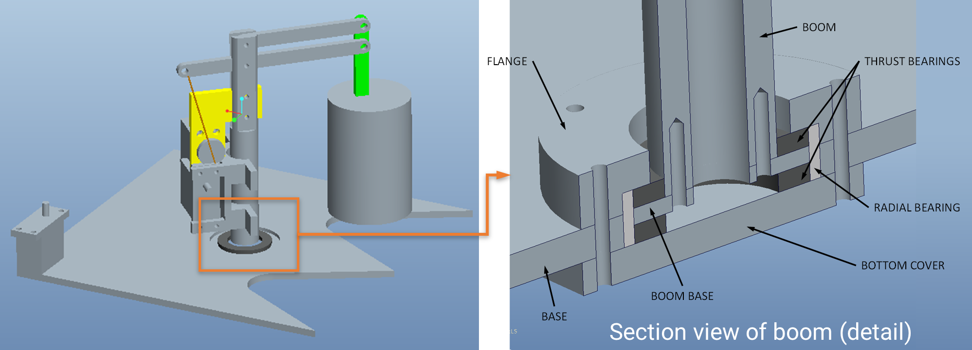
A view of the initial CAD model shows the ideas for the boom
taking shape, with a four-bar mechanism used to ensure a
vertical orientation and precise placement of the can.
The detail cutaway view shows the design for the thrust
bearing, which would minimize friction on swiveling and
ensure precise can placement.
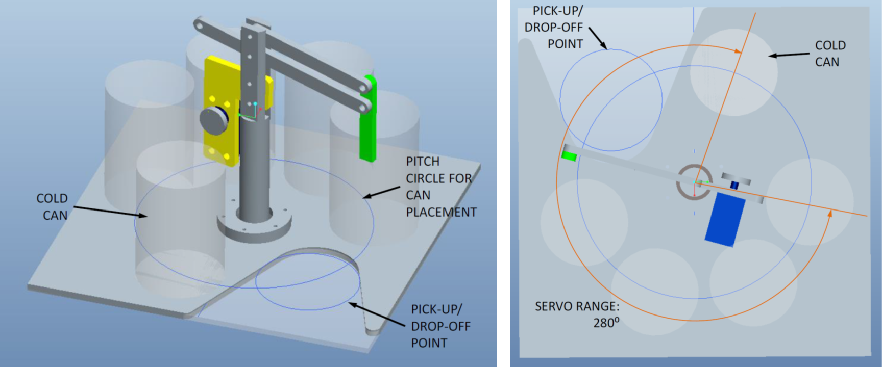
Next, I finalized the shape of the platform and the dimensions of the hoisting mechanism. We decided that an evenly-spaced arrangement of cans would leave us with space for only one cutout, necessitating two passes across the can collection region. The dimensions of the “can-catcher” and the pitch circle of the cans were finalized. This arrangement allowed the placement of the “cold can” at a location that can be accessed regardless of its position in the pick-up queueing order, so that it can be dropped off last as required.
A view of the initial CAD model shows the ideas for the boom
taking shape, with a four-bar mechanism used to ensure a
vertical orientation and precise placement of the can.
The detail cutaway view shows the design for the thrust
bearing, which would minimize friction on swiveling and
ensure precise can placement.
The design of the gripper came next. While my initial concepts for the gripper used an electromagnet, we quickly discovered a heating issue. Tim quickly came up with an alternate design using a gripper with a slight undercut that could catch on to the lip of each can. The gripper was laser-cut, and glued together using three layers of acrylic per jaw.
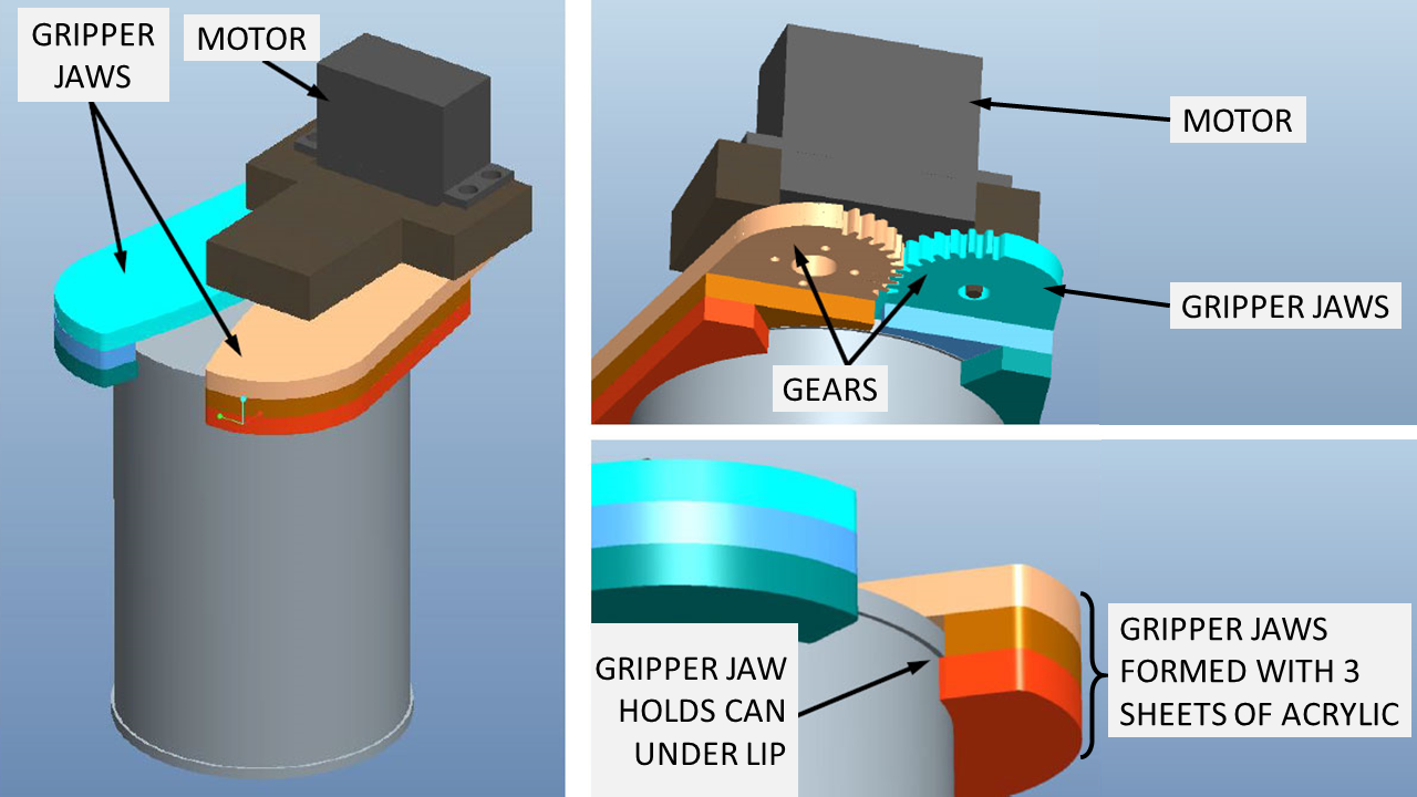
Design of the gripper shows its construction with three
sheets of acrylic, creating an undercut as shown that holds
on to the lip of the can.
The gripper jaws mesh with each other via spur gears, and
are operated with a single servo motor.
Testing and Final Run
The gripper and boom were operated using servo motors. Initial tests with the cans helped us iron out balancing issues (note the counterweight in the video below), and fine-tune the right swivel speed when moving the cans: too fast, and this happened:
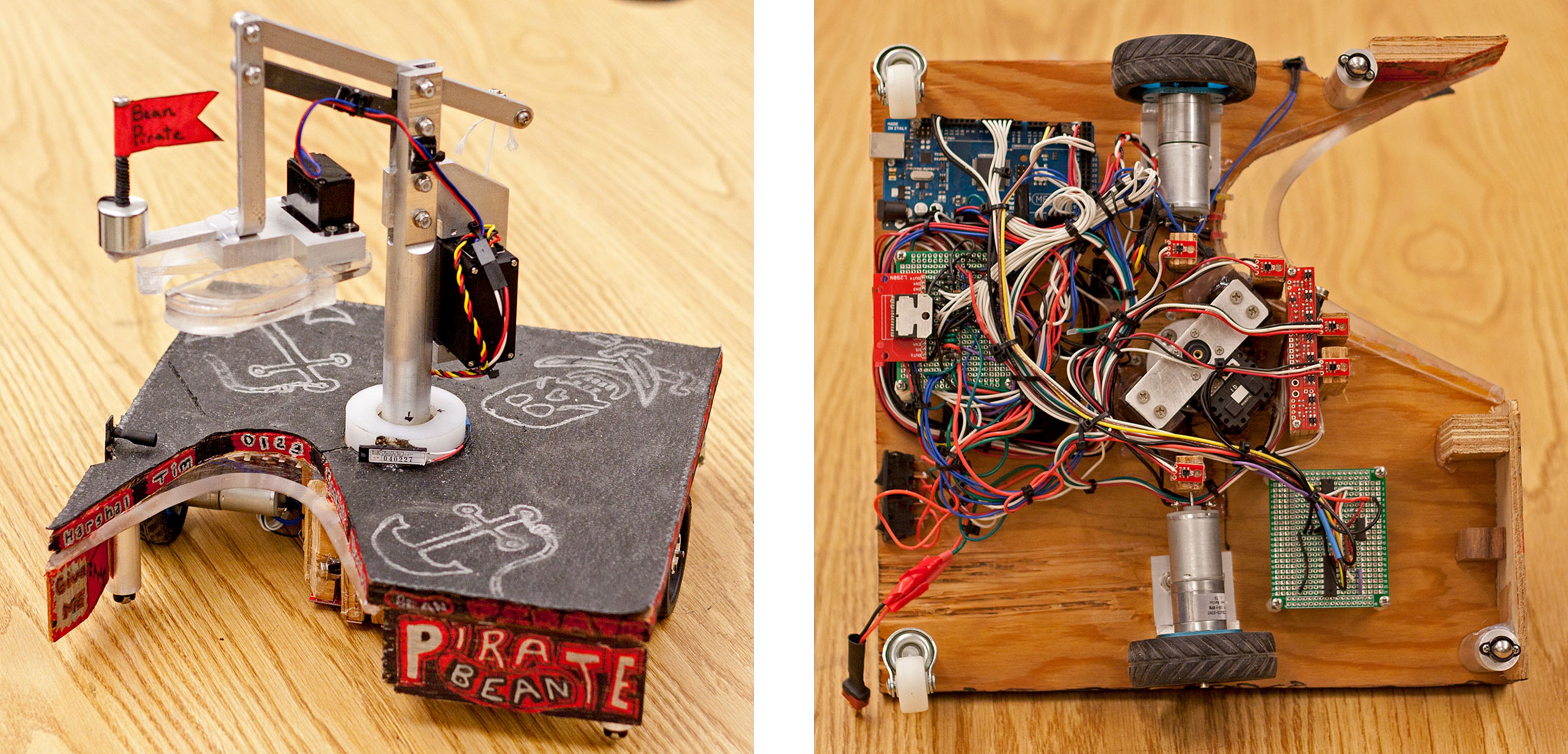
The wheels were bought-out parts, independently powered 2WD robot kit units (see photograph of undercarriage at the top of the page). This simplified steering and propulsion at the same time, which came handy when fine-tuning our line-following algorithm. As seen in the video above, the boom assembly was machined (by Tim) in aluminium, and Denise & Tim designed and put together the circuit.
The final run worked perfectly until the very end, when a glitch in our winching code prevented the cans from being dropped off at the chute.
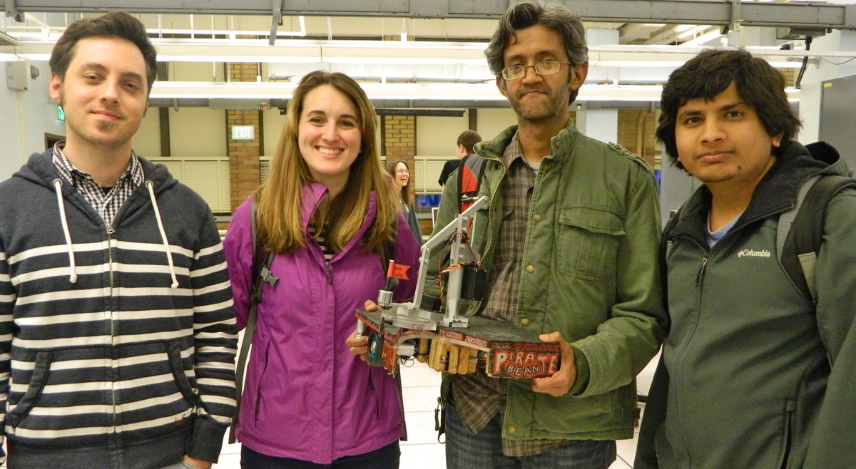
This was a tough challenge, with only one team in 6 actually completing the challenge. Our team was voted “best in show” by the class, a triumph that perhaps does not entirely register on our tired faces (photo credit: Purdue ME 588 course page).
Documentation
For more details, including circuit design, bill of materials, and Arduino code, please refer to the attached report below.