Insufflator Trocar Redesign
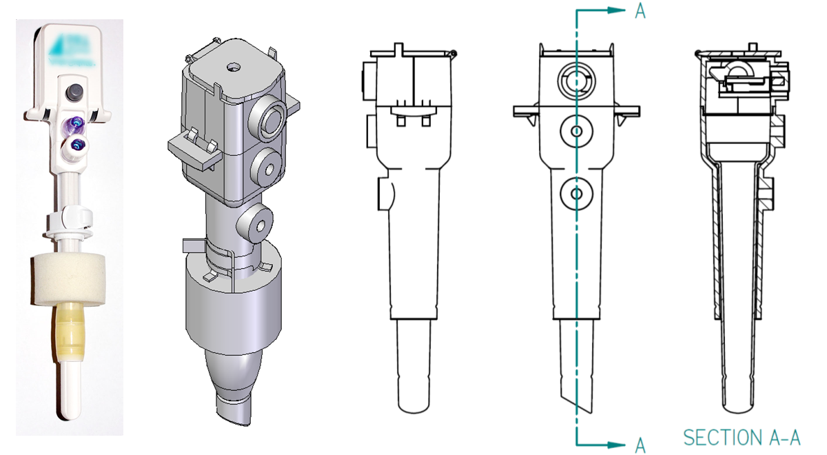
The existing and redesigned versions of the insufflator
trocar.
The image on the far left shows an existing insufflator, and
the images to its right show the Computer-Aided Design (CAD)
model and orthographic views (done in first-angle
projection) of the redesigned version.
This project, executed in Fall 2009 as part of a graduate course in Design for Manufacturability at Purdue, focused on redesigning products in order to reduce part count and assembly effort. Our team was given the task of redesigning an insufflator: a device used in laparoscopic surgeries to create a reliable and clean channel connecting the abdominal cavity and external environment. The purpose of this device is to inflate and deflate the body cavity, and to serve as a channel for inserting endoscopic instruments into the cavity.
Challenge
The problems reported in the current design included leakage
from the balloon, which in turn increased the risk of leakage
from the body cavity.
The latch on the sponge collar
(indicated in
Our goal was to redesign the insufflator trocar to address these issues, and in addition focusing on reducing part count, and manufacturability/assembly issues. Our team had five members: Pat Cook, Feifei Jiang, Somesh Khandelwal, Rachel Narciso, and me.
My Role
I took on the responsibility for the majority of the design and CAD (computer-aided design) modeling of the trocar assembly.
Design
We used a standard Quality Function Deployment (QFD) exercise to determine the main requirements and features to address. Requirements and features were obtained from interviews with a representative of the manufacturer of the insufflator (who was also part of this class) and through a study of brochures and manuals. We used a House of Quality to identify requirements and features that we needed to focus on.
Our conceptual design focused on the body of the trocar, specifically on combining the tube section and the obturator sections into one unit, which would reduce the number of joints, and hence the leakage.
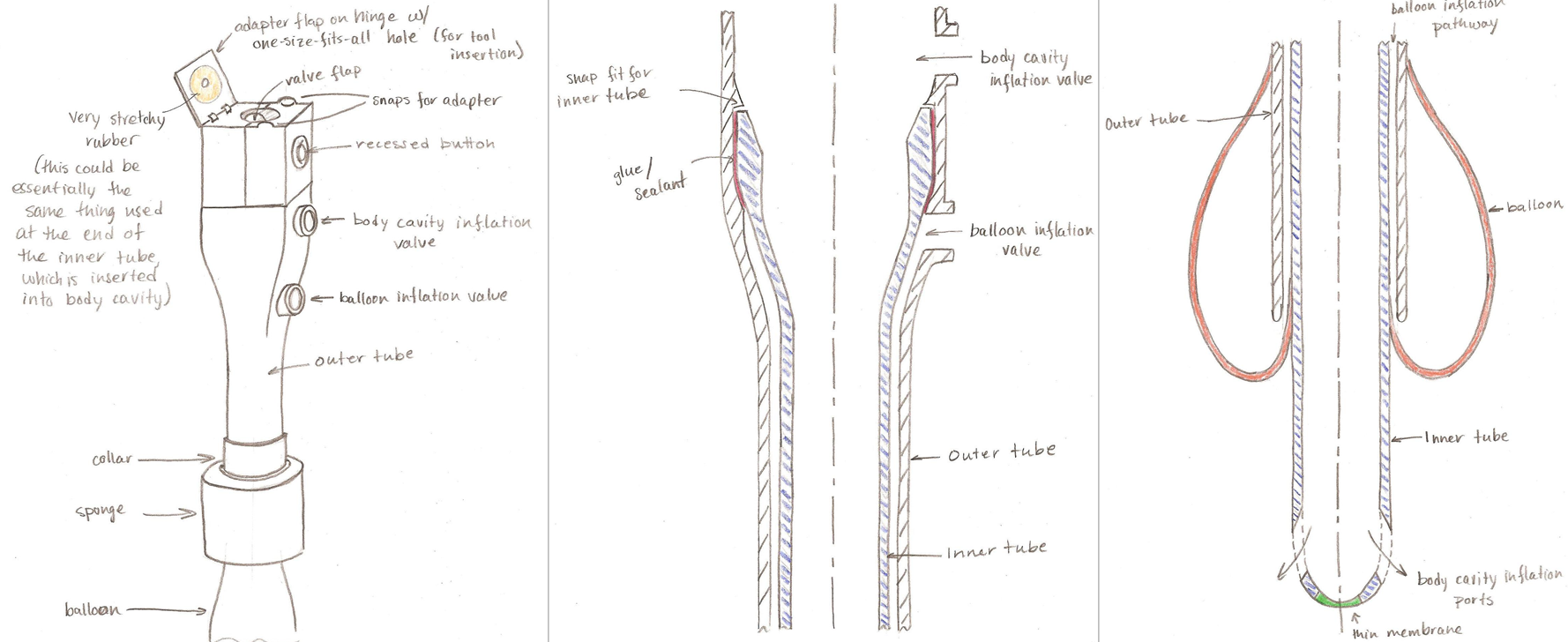
Concept sketches focused on component reduction at the valve
end on top as well as on the body and tubes.
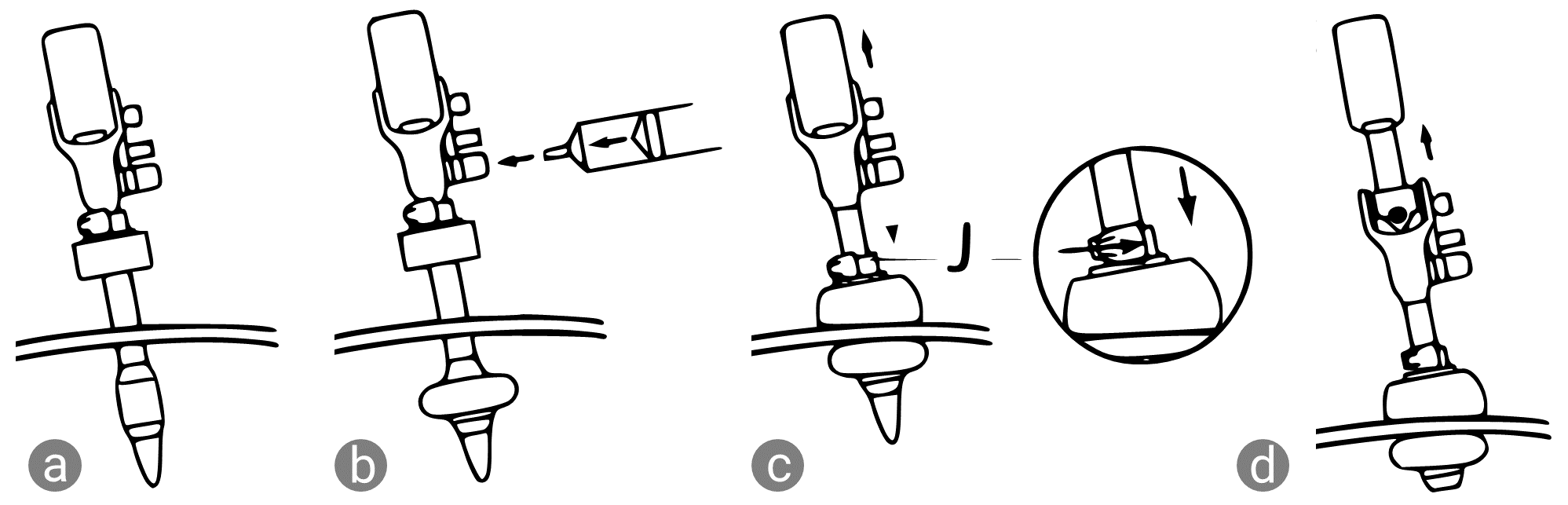
Two concentric tubes form the cannula: the part of the
trocar that is inserted into the abdominal cavity through an
incision.
The inner tube guides air/gases to the body cavity while the
space between the inner and outer tube guides air to the
sealing balloon.
In our concept sketches, we combine the inflation channels
with the canula assembly, since fewer joints
potentially reduce leakage.
Our redesign focused on component reduction, from 33 components in the original design to 20 in the new design (including sutures, membranes etc. not shown in the CAD models below). We split the trocar assembly into two: the upper housing, consisting of the desufflation & instrument insertion valves, and the cannula housing, consisting of the inner and outer tubes, the sealing balloon, and sponge.
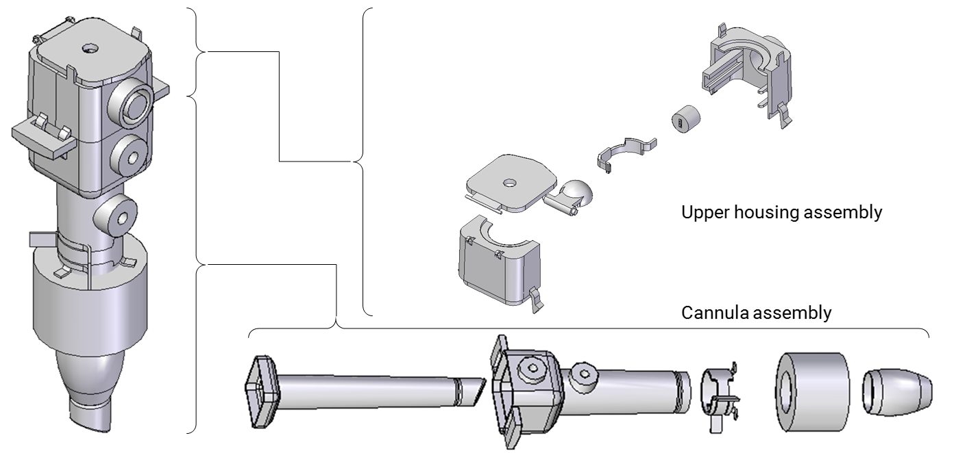
The final design of the trocar assembly is split into two
subassemblies.
The
In the cannula assembly, the main changes were to combine the tubes with the lower housing of the channels that inflate the sealing balloon and the abdominal cavity. Sealing between the inner and outer tubes was achieved by gluing the contact area designed between the two, where the inner tube rests on the inner inclined surface of the outer tube. The inner tube has a beveled end to ease insertion into the body cavity.
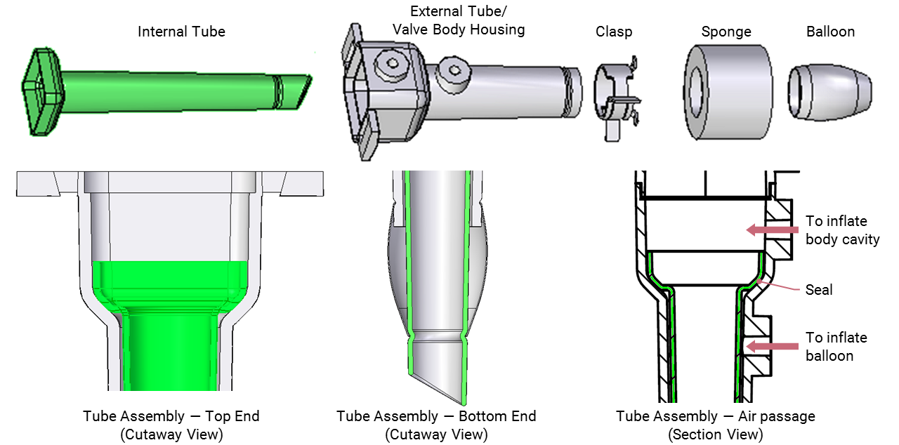
The inner tube (shown in green) rests on the inclined inner
surface of the outer tube, as shown in the cutaway view on
the left.
The joints between the air channels and the respective tubes
are eliminated, reducing the chances of leakage.
Similar component-reduction exercises were carried out at the clasp or the collar of the cannula assembly. We replaced the complex clasp assembly of six components, with a single component which would be stamped and formed from a single piece of metal.
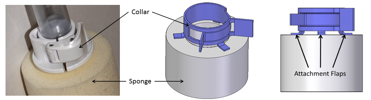
The collar or clasp assembly was originally assembled from
three injection-molded parts and three pins.
Our design reduced it to a single component, a form of
“circlip” that is used in closing tube
connections.
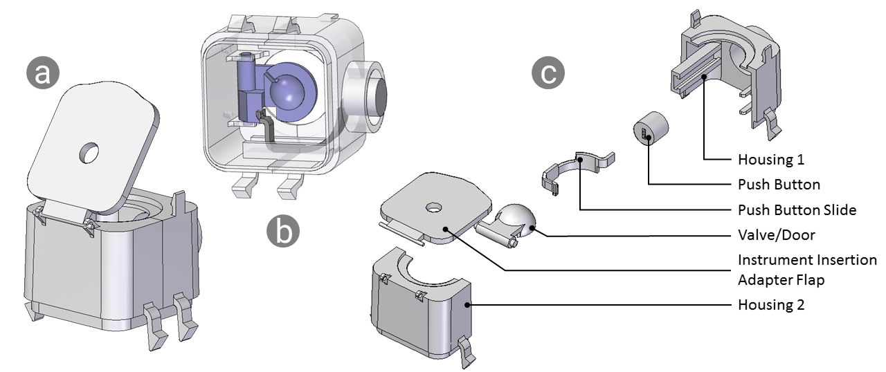
The upper housing assembly was more complex owing to its moving parts. In the original design, the upper housing contained all the valves and air channels, but in the redesign, the channels were now part of the cannula assembly. We designed the upper housing to snap into the cannula assembly using two pairs of snap fit features. We designed the desufflation button (which releases air from the abdominal cavity once the surgery is complete) to be recessed to prevent accidental desufflation when handling the trocar. The assembly and exploded view is shown below.
Explain main considerations here.
The upper housing assembly
The upper housing bodies were the most complex of the designed components. I designed these to be injection moldable, with attention given to tooling direction, parting line location, draft angles, and minimizing undercuts. The undercuts in the current design are the snap-fit hinges for the valve door and the tool insertion flap, and the desufflation button cavity with corresponding slider guides and locating ribs. These can be molded with the use of lifters or sliders. The two halves are glued together, and the upper housing assembly is snap fit into the cannula assembly, reducing some of the assembly effort.
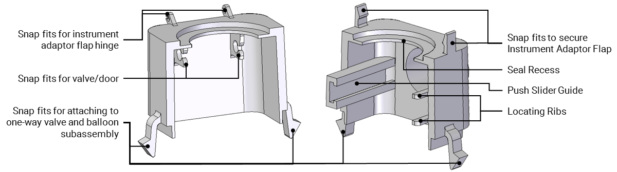
These two components are designed to be injection molded,
with considerations given to tooling direction, smooth wall
thickness transitions, and undercuts, among other aspects of
design for injection molding.
Limitations
While this redesign exercise was conducted primarily to improve manufacturability and assembly, there were some tradeoffs: the increased outer diamater of the cannula would result in increased patient discomfort, the instrument adapter flap requires a molded-in rubber & plastic combination that would be expensive to manufacture, and the construction of the cannula reduces the sponge travel range along the length of the cannula, reducing the range of insertion into the abdominal cavity.
Documentation
For more details, including requirements analysis, failure mode effects analysis, structural analysis, and tolerance stack-up, please refer the report and presentation below.